 |
 |
|
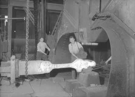
The Forge Forging
gives steel great strength, in this photograph taken in 1954 we see
our Vulcanists using a 10 ton (20000lb) steam hammer to work the red hot metal that will become a
locomotive connecting rod one of the most stressed parts of a
locomotive.
|
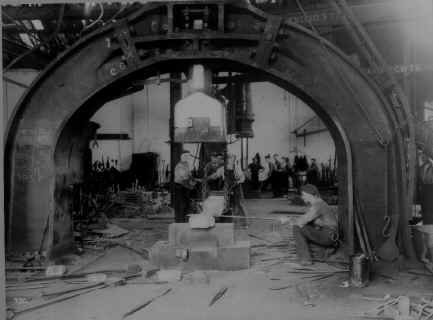
The Forge If
you thought that the hammer to the left was big then have a look at this
one which was the largest in the foundry at 50 ton (100000lb). This one
is again at work forging a connecting rod, the larger hammer was
required to work the side faces of the rod which had a larger surface
area requiring more greater force to work. |
|
Click
here for Video
|
|
|
|
|
|
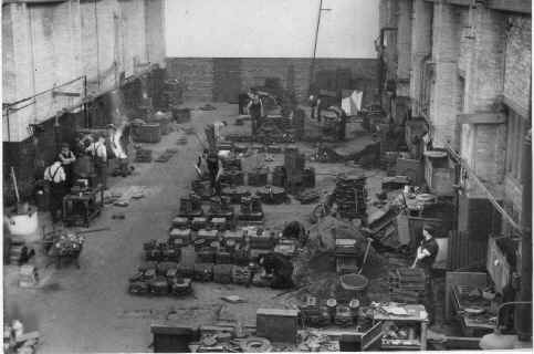
Non Ferrous
Foundry
A lot of the
smaller bits and pieces required to build the Vulcans finished products were made in-house from Non-Ferrous metals (copper alloys) such as
Brass, Bronze & Gun Metal. Such items would include steam fittings,
nameplates, makers plates, whistles, bearings, handles and other bright
work. Amazingly we have dated this image to 1953 by reading the headline of
the newspaper in the wooden bench seen at the bottom right of the photo!
|
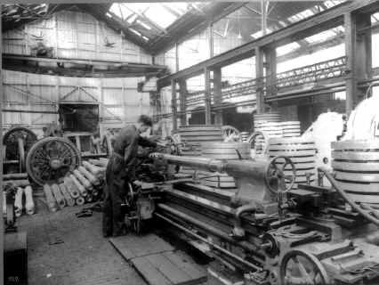
The Wheel Shop
Here we can see axles being turned on a Craven
centre lathe ready
for assembly. Cast wheels and their steel tyres lying stacked all around the man working the lathe.
|
|
|
|
|
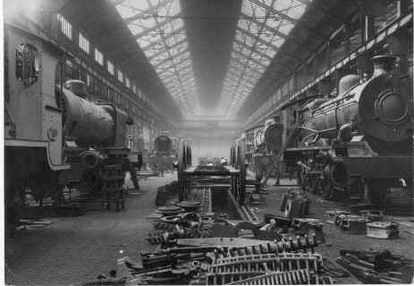
The Erecting Shop
This is the part of the foundry where all
the ingredients that made up each locomotive were assembled or erected.
Boilers mounted in frames would be dropped onto their axles and wheels
and all the other parts attached. In the photo you can see many such
parts strewn over the floor in the foreground.
|
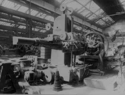
Machining Axle Assemblies
This photograph shows an axle assembly
undergoing a final machining operation on a Richards No. 5 horizontal
borer. The machine
is obscuring the tooling but the chap seems to be aligning it on the
centre of the axle, any ideas?
|
|
|
|
|
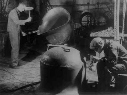
Sheet Metal Work
Ever wondered how the curvy bits were made
like the dome on top of the boiler that covered all the insulation and the
boiler itself. Well here we see two artisans working sheet metal by hand
with the aid of heat and a few hand tools. Even when most of the
locomotive was made with the aid of machinery some bits were still more
cost effectively made by hand.
|
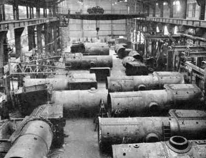
Boiler Shop
This photograph is a good view of the boiler
shop a distinct change from the more organised machine shops. Boilers
being the largest and most awkward locomotive components would be
constructed in a large open area with a high capacity overhead crane
available. As the boilers were constructed they would be rolled from one
side to the other or upended to enable all the hot rivetting to be
completed.
|
|
|
|
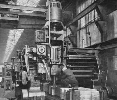
Holroyd Three Headed Slotting Machine
Built by the foundry in 1912, rough flame cut
frames would be finish machined in one go to eliminate the risk of stress
cracking from the flame cutting. The machine was completely rebuilt in
1946 and had a bed length of 90' (over 27m). This photo shows it in its
rebuilt state machining a stack of 16 frames with the other heads hidden
behind the first.
|
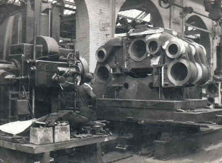
KEARNS Horizontal Borer
Ken Johnson using a Kearns No. 5 Borer to
bore out steam cylinders in the late 1940's or early 1950's.
|
|
|
|
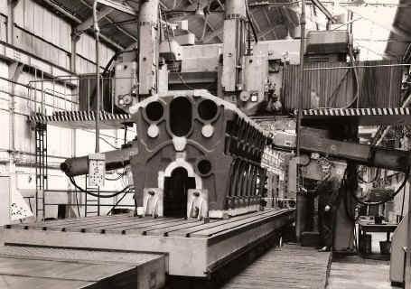
Noble & Lund Plano-Miller
Les Jarrett machining a crankcase for a
A.T
12 cylinder 'V' form Diesel in Bay 3 or 4?.
|
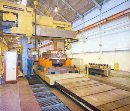
Waldrich Siegen Plano-Miller
Les Jarrett again with
the Waldrich Siegen installed in Bay 4 (approx
1980) it replaced the old Noble & Lund Plano-miller
|
|
|
|
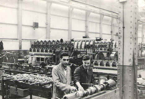
Camshaft Timing Roy Whittaker has sent in this photo taken in 1958
that shows Roy with a student from Jordan. Roy is assembling an
English Electric 8SRK camshaft for Argentina Railways. At this time in
1958 only the 4, 6, 8 cyl engines were assembled at Vulcan (you can
see examples in the photo) the 8, 12, 16 V engines were still being made
and tested at English Electric Preston works and delivered to Vulcan Works for fitting
into the locomotives.
|
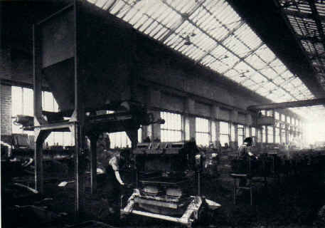
Jackman Turnover Machine in the Iron Foundry
Jackman Turnover Machine installed in the
iron foundry in the early 1950's.
|
|
|
|
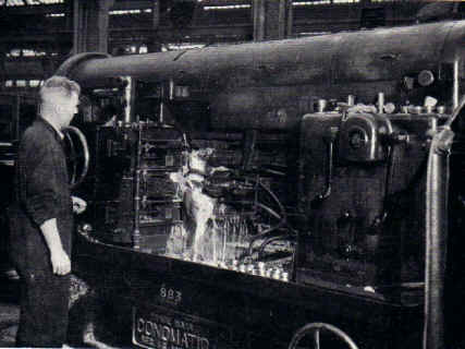
Conomatic 6-Spindle Automatic Lathe
6-Spindle Conomatic Lathe for the continuous
production of flexible firebox stays, one of 2 machines specifically
dedicated to their production after WW2.
|
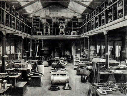
Pattern Shop 1902 Patterns
(made of wood) were used in the production of castings in the ferrous and
non-ferrous shops and were used to produce imprints of the required items
in the two halves of the sand filled casting boxes.
(If you can describe this better in one sentence then let me know)
|